File ManagerAccount SettingsAccessing The SoftwareSupportTeam ManagementFull Demos
Certification
This documentation applies to AISC 360-10 (14th Edition) or AISC 360-16 (15th Edition) in either ASD or LRFD provision.
Once you have chosen either ASD or LRFD you will be presented with the Details tab as shown in the figure below.
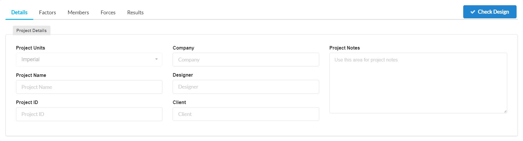
This is where you are able to insert project details such as:
Both ASD and LRFD are used for designing steel members in accordance with American Standard AISC 360. However the Allowable Strength Design (ASD) design software applies a quasi-safety factor approach to evaluating allowable strength. Whereas Load and Resistance Factor Design (LRFD) is also known as limit state design (LSD) and requires that the structure satisfies the Ultimate Limit State (ULS) and the Serviceability Limit State (SLS).
The main difference you will notice is in the Factors tab as shown in the figure below for ASD and LRFD respectively.
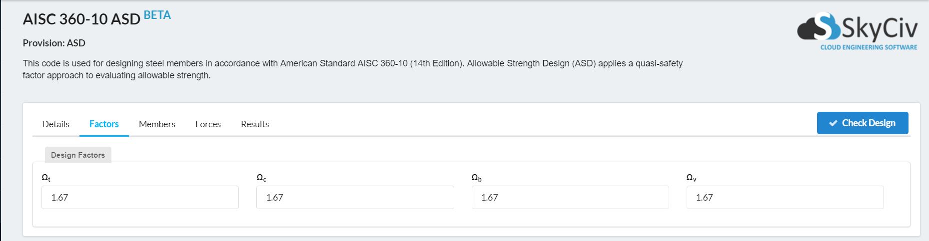
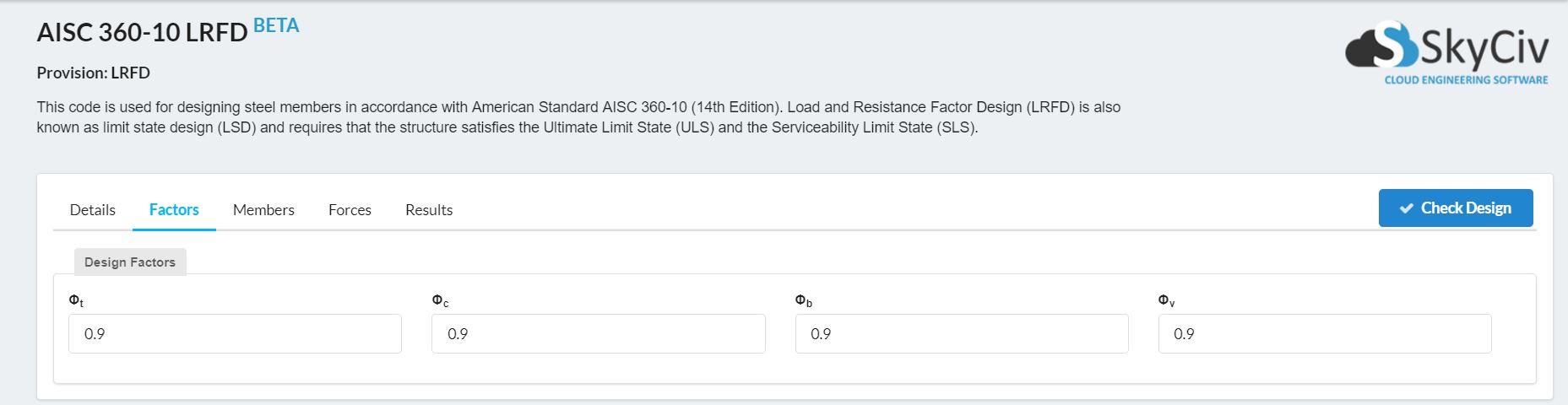
As you can see from the figures, ASD has factor of 1.67 where as LRFD has factors of 0.9. These numbers come from the American Standard AISC 360 but are able to be modified if needed before the final Design Check.
The Members tab is where you can define any members that you are working with by clicking the + Add Member button.
Each Member you add must include a Member ID, a Material ID and a Section ID as well as an array of factors shown in the image below.
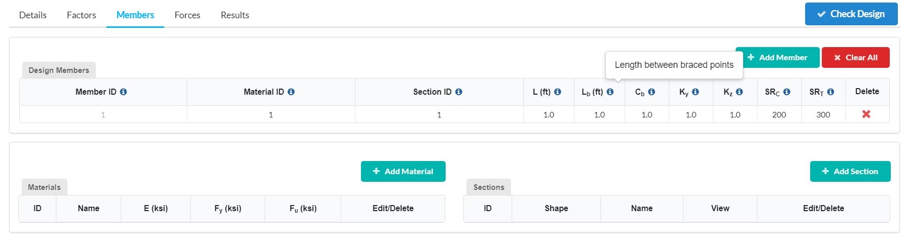
If you are unsure of what each factor represents you can hover over the i as shown above to give a brief discription.
Once you have added your members in you need to specify what materials you are going to be using. This is done by clicking the + Add Material button which will open up the following menu.
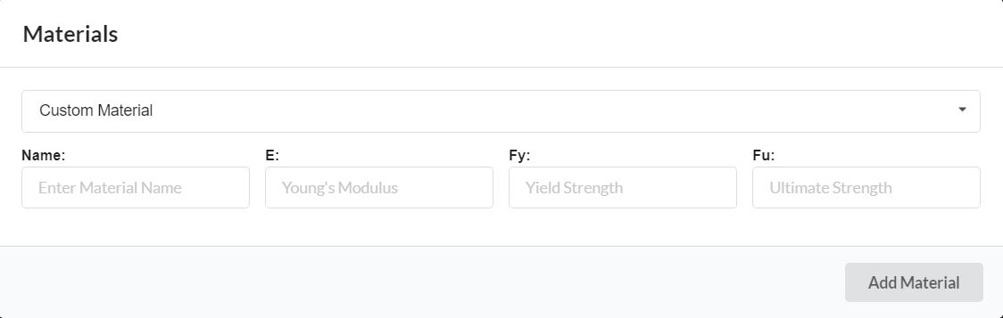
In the Materials menu you can either create a Custom Material by entering a Material Name, a Young's Modulus, its Yield strength and its Ultimate strength; or choose from the list of predetermined materials which includes:
Once you have added your materials in you need to specify what sections you are going to be using. This is done by clicking the + Add Sections button which will open up the following menu.
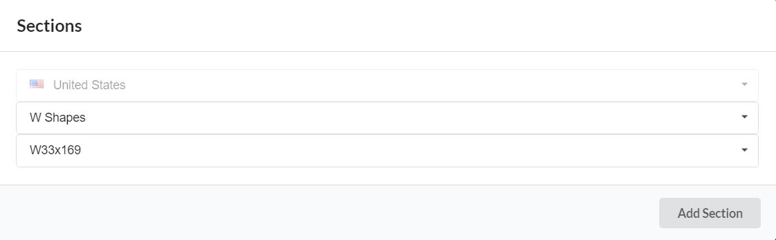
In the Sections menu you can choose from the list of preset United States Sections which include:
After which you can go on to choose the exact section you would like from the extensive lists included.
The Forces tab is where you can define any forces that are applied to your members by entering in the relevant forces and then clicking the Apply button.
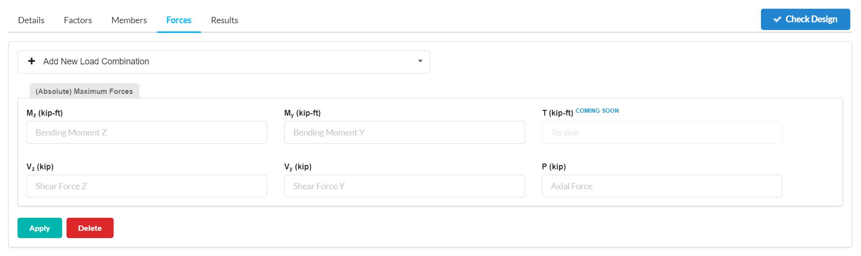
Additional Load Combinations can be added by clicking the + Add New Load Combination button in the Load Combination drop-down menu.
Once you have designated your Details, Factors, Members and Forces click the Check Design button shown in the figure above to run the design check which will then mean you can check the Results tab as shown in the figure below.
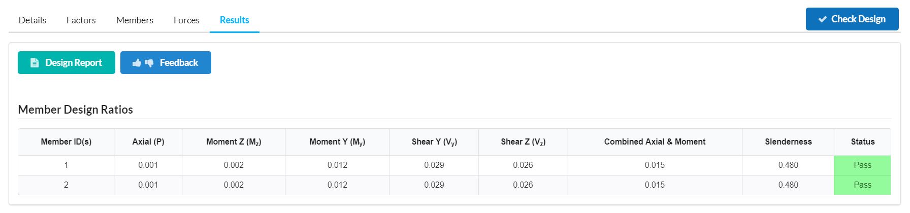
You are also able to create a Design Report by clicking the Design Report button.
Your Company logo will be included on the Design Report along with many other great account features if you have an Enterprise Account.