File ManagerAccount SettingsAccessing The SoftwareSupportTeam ManagementFull Demos
Certification
Member offsets are small displacements to a member’s position to reposition itself to a location closer to its real world representation.
By default, SkyCiv’s S3D software joins members node to node where a node is located at the cross section's centroid. Aesthetically, this default behaviour creates an overlap of some members which realistically could not occur. In addition, small moments or forces can be present in real world structures due to the adjacent members not actually being joined centroid to centroid. Member offsets are hence used to fix these issues.
Member offsets are defined by a three string input as follows [x-axis, y-axis, z-axis], this specifies that the members is offset by a specified value of millimetres in the direction of the designated local axis. The local axis must be used for the offset command due to the confusion that can arise within a three dimensional space when two members are on two totally different planes. For example if a members is on a diagonal to the global axis offsetting it via global measurements would be difficult and time consuming.
Member local axis’ can be displayed onto the wire framed view by going into the visibility settings and turning them on as shown below:
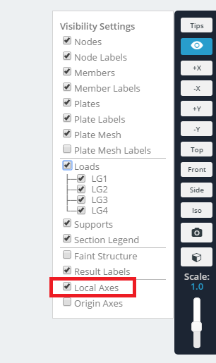
The colored lines on each member represents axis local to the member. Green indicates the direction of the local Y-axis; red indicates the direction of the local X-axis; and blue indicates the direction of the local Z-axis.
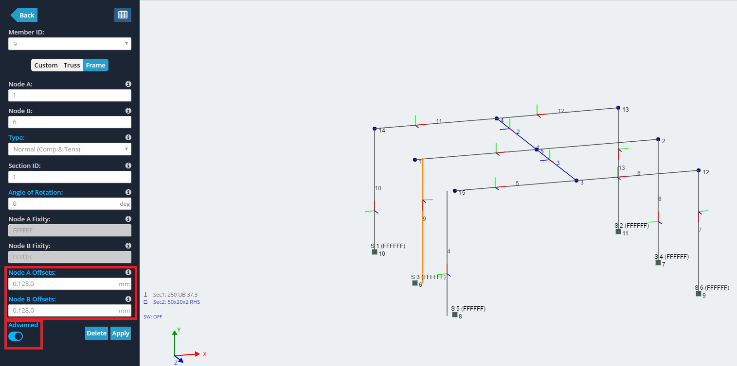
A member can be offset by clicking on the member and entering the value of the offset in the corresponding axis section of the following [x-axis, y-axis, z-axis], originally set as [0,0,0] due to the lack of initial offset. Using a negative number will offset the member in the negative direction as the local axis.
To access the offset options, make sure you've toggled the "Advanced" switch to the on position.
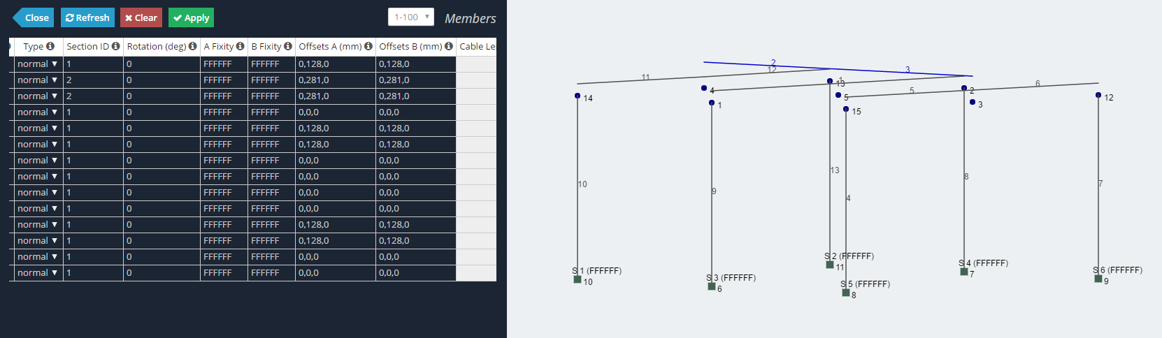
Shown below is an example of a frame without any member offsets. Note that offsets to a member can be made at a single end or both ends as show in the datasheet view of the structure.
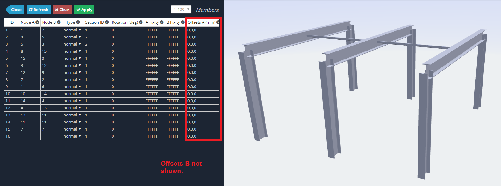
You can see above that the corners of the frame members are over lapping and that the purlin is sitting within the frame rafter rather than on top.
Shown below is the same frame but with the use of member offsets:
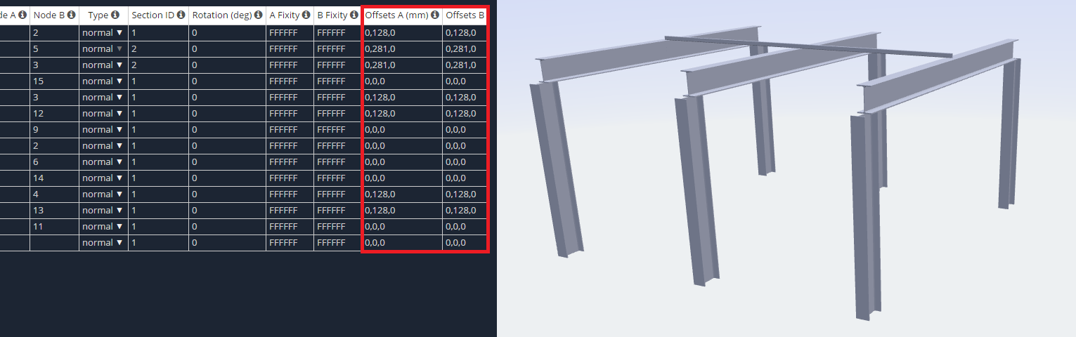
You can see above that the rafters now sit on top of the columns instead of within them and the similarly with the purlins on the rafters.
Shown below is the same frame but in the wired frame view:
Although the members do not look connected anymore it will still model as a complete frame with rigid connections.