File ManagerAccount SettingsAccessing The SoftwareSupportTeam ManagementFull Demos
Certification
Nodes are points in space which specify the location of features such as members, plates, loads, and supports.
Nodes are added using x, y, z coordinates. Users can be enter nodes via a form or a datasheet. They are represented as a blue dot on the main graph, and have a node number assigned to the upper right of the node.
Nodes cannot be free; they must be connected to at least one member or plate for the code to solve successfully. These are what connect all the elements of your structure.
To use nodes to specify the location of these features simply:

There are a few different ways you can add nodes into Structural 3D. We've made the software fairly intuitive and easy to use, so we hope you find your preferred way to enter in nodes below:
When you open the software, you will see a button on the left that says Nodes. Clicking this will open up options for you to enter in the X,Y and Z coordinates of your nodes.
SkyCiv's datasheet allows you to enter in a great number of nodes in a quick and easy tabulated format. Use Enter and Tab keys for quick entry, click and drag to repeat cells and sort the table by clicking the column headings. You can even copy and paste values from Excel. The datasheet is particularly useful if you need to be able to see all your other node coordinates as a reference.
To get access to the Nodes datasheet, click Nodes on the left menu and then the blue grid button at the top of the form. It should open up the datasheet as follows:

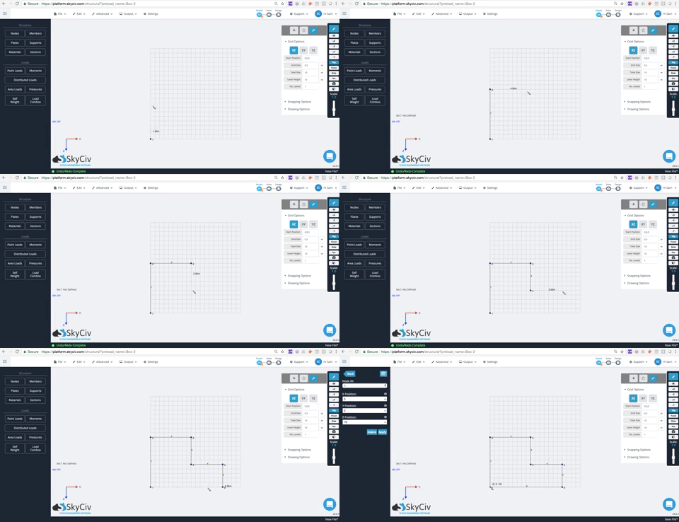
Want the freedom to plot nodes on a grid or along a particular axis? SkyCiv has a great set of pen tool and grid features that makes this easy.
