Using the SkyCiv Load Generator for Comisión Federal de Electricidad (CFE) Manual de Diseño de Obras Civiles – Diseño de viento (México) Wind Load Calculations
To calculate the wind load pressures for a structure using SkyCiv Load Generator, the process is to define first the code reference. From there, the workflow is to define the parameters in Project Details, Site Data, and Structure Data, respectively. However, free users can only use the calculation for a gable and open pitched/duopitched roof for a maximum of 3 solves per week. With a Professional Account or by purchasing the standalone Load Generator module, you can use all the features of this calculation as long as you want You can purchase the standalone module thru this link.
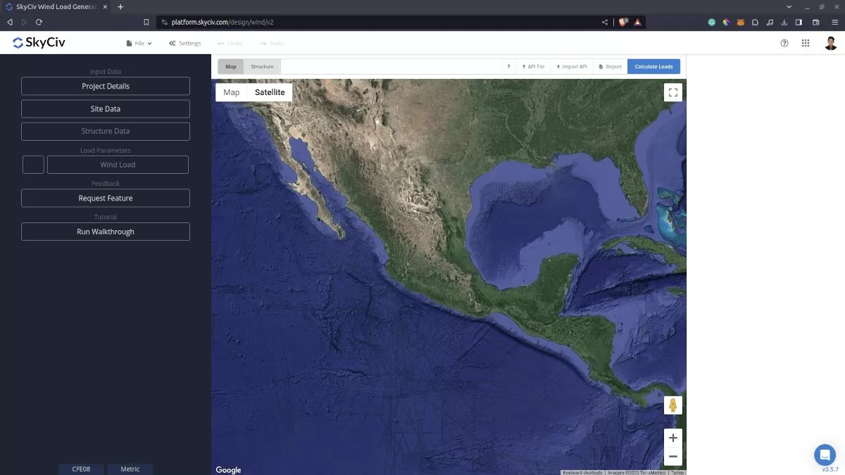
Figure 1. SkyCiv Load Generator UI
Site Data
Calculating wind speeds can be a complex process in CFE Viento for locations in Mexico. That’s why SkyCiv has developed an online wind load tool to help calculate design wind speeds and pressures via our interactive Google map. The location is specified with the project address or by clicking and dragging the marker:
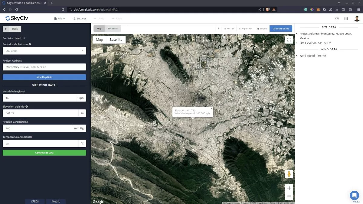
Figure 2. Site data of SkyCiv Load Generator
SkyCiv has digitalized the map as per the paperback standard. This means, you can simply enter in the site location and the software will automatically pull the wind speeds based on this input. There is a limit to how many times the wind speed can be calculated on the free tool. The software will use our internal interpolator to calculate values between the contours, to ensure accurate wind speeds are used in your designs.
Site Input Parameters for Wind Load Calculation
Periodos de Retorno – This value is used to determine the regional wind speed based on Section 4.2.2.1. The options are 10 years, 50 years and 200 years.
Project Address – Used for getting the nearest wind speed based on the Periodos de Retorno selected
Basic Wind Speed – the basic wind speed to be used in calculating the design wind pressure. This is automatically determined based on Periodos de Retorno and Project Address and can be modified by the user
Presión Barométrica y Temperatura Ambiental – It is used to calculate the correction factor for temperature and height with respect to sea level. The default values are 760 mm Hg and 25 degrees Celsius, respectively.
Once the parameters above are completed, we can click the “Confirm Site Data” to check if our input is okay (will change the font color of the button from white to green). After this, we can now proceed to the Structure Data section.
Structure Data
The structure data and the wind and snow parameters are separated into different sections. You need to define first the Structure you are analyzing. Currently, only Building structure is supported in CFE.
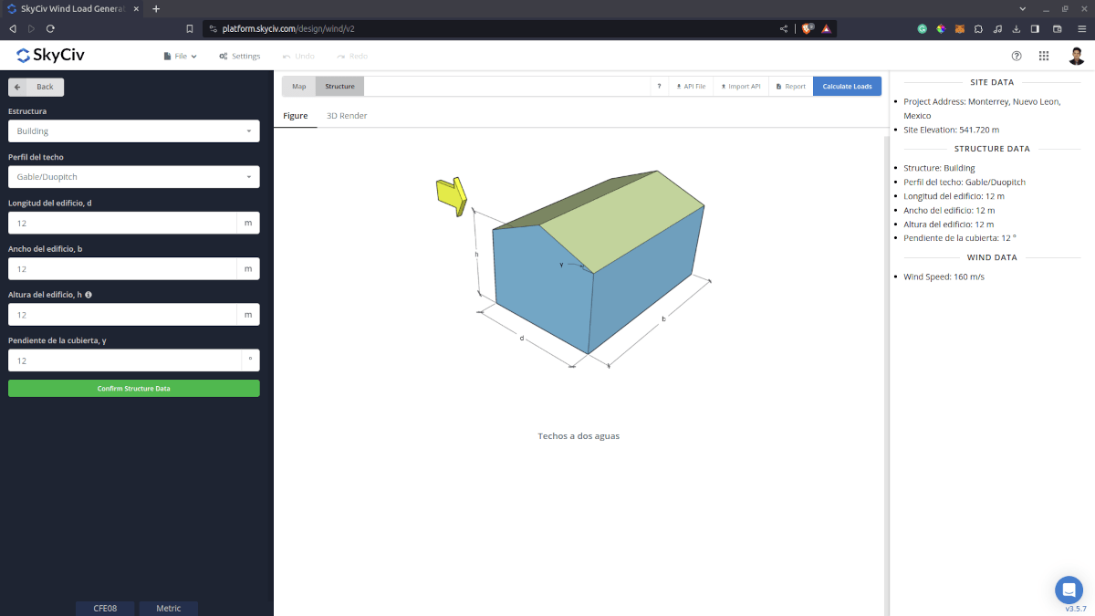
Figure 3. Structure data input for buildings.
For building structure, we need to fill the structure dimensions as shown in the building figure above. The option for the roof profiles are as follows:
- Gable
- Monoslope
- Hip
- Pitched (open gable)
- Troughed (open inverted gable)
- Open Monoslope
For free users, only Gable and Pitched roof are available for Building. Once you have completed all the structure data inputs, you can visualize the structure by clicking the 3D Render at the right side. In addition, note that the building length is defined as the dimension parallel to the wind direction (as shown in arrow) and the building length is perpendicular to the wind direction
Structure Input Parameters for Wind Load Calculation
Perfil del techo – Used in pressure coefficient values based on the selected roof profile and roof pitch angle
Longitud del edificio– the dimension parallel to the wind direction as defined in CFE. Used in calculation of pressure coefficients
Ancho del edificio – the dimension perpendicular to the wind direction as defined in CFE. Used in calculation of pressure coefficients
Altura del edificio – the dimension of the structure from ground to the middle height of the sloping roof. Used in calculation of velocity pressure
Pendiente de la cubierta – the roof slope in degree. Used in calculation of pressure coefficients
Once the parameters above are completed and validated (clicking Confirm Structure Data), we can now proceed to the Wind Load Parameters section.
Wind Data
To proceed with our wind load calculation, we need to check the checkbox first beside the Wind Load button. By default, this is checked when the site wind data has been defined.
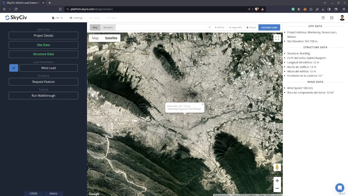
Figure 4. Checkbox for Wind Load Data.
The next step, is to define the Wind Source Direction and the corresponding Categoría del Terreno Según su Rugosidad of the upwind area.
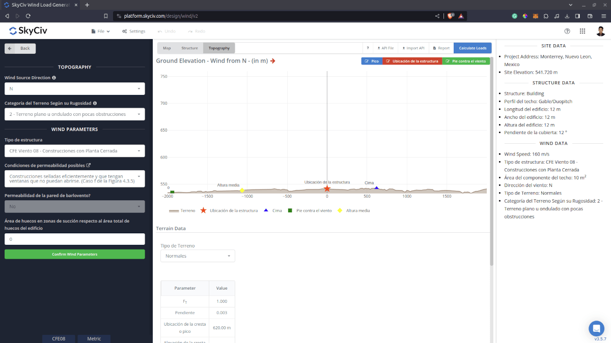
Figure 5. Elevation Data from Google Maps for upwind (left) and downwind side (right).
Wind Input Parameters for Buildings
Type of Structure – set CFE Viento 08 – Construcciones con Planta Cerrada or CFE Viento 08 – Techos Aislados
Condiciones de permeabilidad posibles – For calculation of internal pressure coefficient Cpi for enclosed roof profiles. Can be defined by clicking the label to show the options.
Área de huecos en zonas de succión respecto al área total de huecos del edificio – For wall condition with dominant opening, used in determining the internal pressure coefficient Cpi for enclosed roof profiles
Área de revestimiento de paredes – Used in calculating the design wind pressure for wall cladding or components
Área de revestimiento de techo – Used in calculating the design wind pressure for roof cladding or components
Wind Blockage – For calculation of net pressure coefficients Cpn for open roof profiles
After all these parameters are defined, the next step is to click the Calculate Loads on the upper right side of the UI.
Results
The results of the calculation are shown as follows:
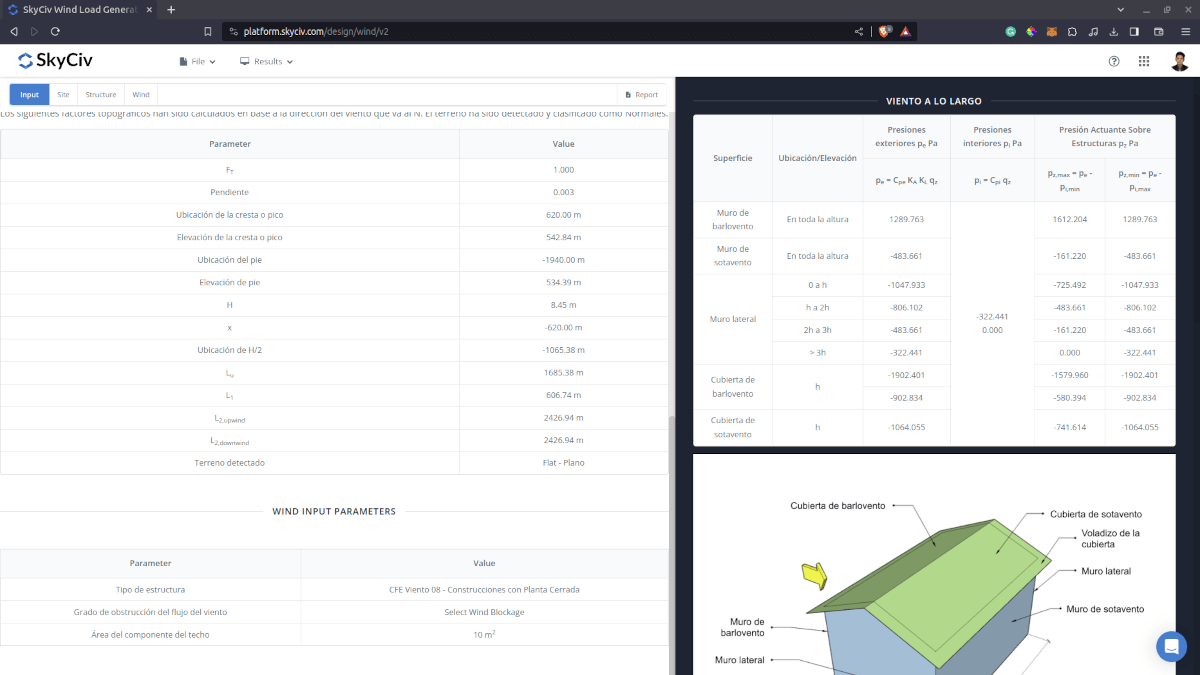
Figure 6. Wind results for Building.
Detailed Calculation
The detailed wind load calculations can be accessed only by Professional account users and those who purchased the standalone load generator module. All the parameters and assumptions used in the calculation are displayed on the report to make it transparent to the user. You can download a sample detailed calculation thru the following links:
CFE Viento 08 – Construcciones con Planta Cerrada
CFE Viento 08 – Techos Aislados
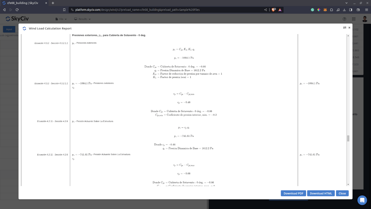
Figure 7. Detailed Wind Load Report.
Para recursos adicionales, puedes consultar estos enlaces como referencia: