Getting started with the SkyCiv-Grasshopper Plugin
Please note that this is the Old version of the Plugin. Please head over to Grasshopper V2 | SkyCiv Engineering for the latest version.
Introduction
This article is about the SkyCiv plugin being developed to transform the complex models built using the unique features offered by GH and to solve/analyse/design the same geometry in SkyCiv S3D platform which is a versatile and powerful analysis tool.
Getting Started
SkyCiv’s plugin allows users to import their complex dynamic models built in GH into S3D for structural analysis & design. The plug-in will handle the complex geometry and transform it by all the necessary information needed for structural analysis (nodes, elements, sections, materials, loads, supports etc…). The plugin will generate the model and output in the form of a json file which can be used on the S3D platform for running the analysis. The subsequent versions will also build on this platform to interlink the analysis results with the country specific designs to fully utilise the SkyCiv’s ecosystem.
For users with access to GH, they can download the plugin from the SkyCiv Plugin store or using the button below:
Previous releases: Grasshopper v6
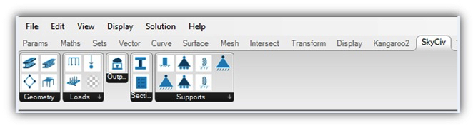
After downloading the file, double click the installer (.exe) file and open Rhino > GH. If the plugin is loaded successfully, the SkyCiv tab and settings should appear under GH tools menu like so:
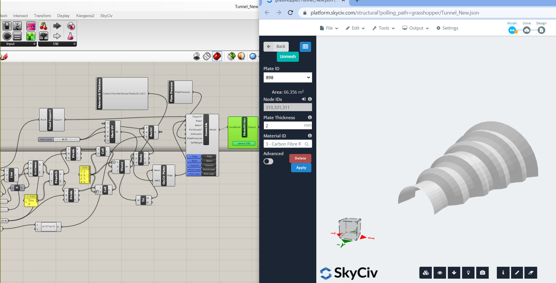
After building your model, you should be able to launch SkyCiv Structural 3D directly from the plugin, using the Output components. You can link your Grasshopper to a Structural 3D model, so as you change the parameters in Grasshopper, the model will instantly update in S3D. In order to do this, you will also need to download SkyCiv Desktop. To do this, login and click the desktop icon on the bottom left corner.
A Typical Workflow for Executing Design through the Plugin
A SkyCiv’s plugin could help compliment the workflow to the engineers, by modelling, saving and solving the analysis and designs for their models. After installation, various tools are visible on the SkyCiv component tab in Grasshopper.
- Users can create the desired geometry using the parametric modelling facilities in Grasshopper.
- The dynamic geometry once ready need to be then transformed using SkyCiv Components to make it ready for analysis/design. (A format compatible with SkyCiv Solver)
- Every solver requires inputs in form of connectivity, boundary conditions, loads and cross sections for carrying out analysis of a geometry based on the principles of Applied Mechanics.
- Using SkyCiv’s plugin, user will have to declare :
- Element definition: Lines and surfaces present in the geometry can be transformed in form of ‘Beams’ & ‘Plates’.
- Boundary conditions in form of assigning Supports to nodes
- Loads: Various types of loads such as Nodal Loads, Distributed loads, Pressures etc are available as a choice to user for assigning them to nodes/Beams/Plates.
- Materials: SkyCiv’s plugin contains Library of materials viz Structural Steel, Concrete, Timber, Glass, Carbon Fibre Reinforced Plastic, Aluminium etc.
- Section Properties: User need to choose the desired cross section amongst the library available based on shapes/profiles and country specific databases
- After assigning the above mentioned parameters for ALL the elements forming as a part of the geometry, the components need to be assembled under the “Assemble Model” tab, where the inputs declared by the user gets collected and arranged into a specific format.
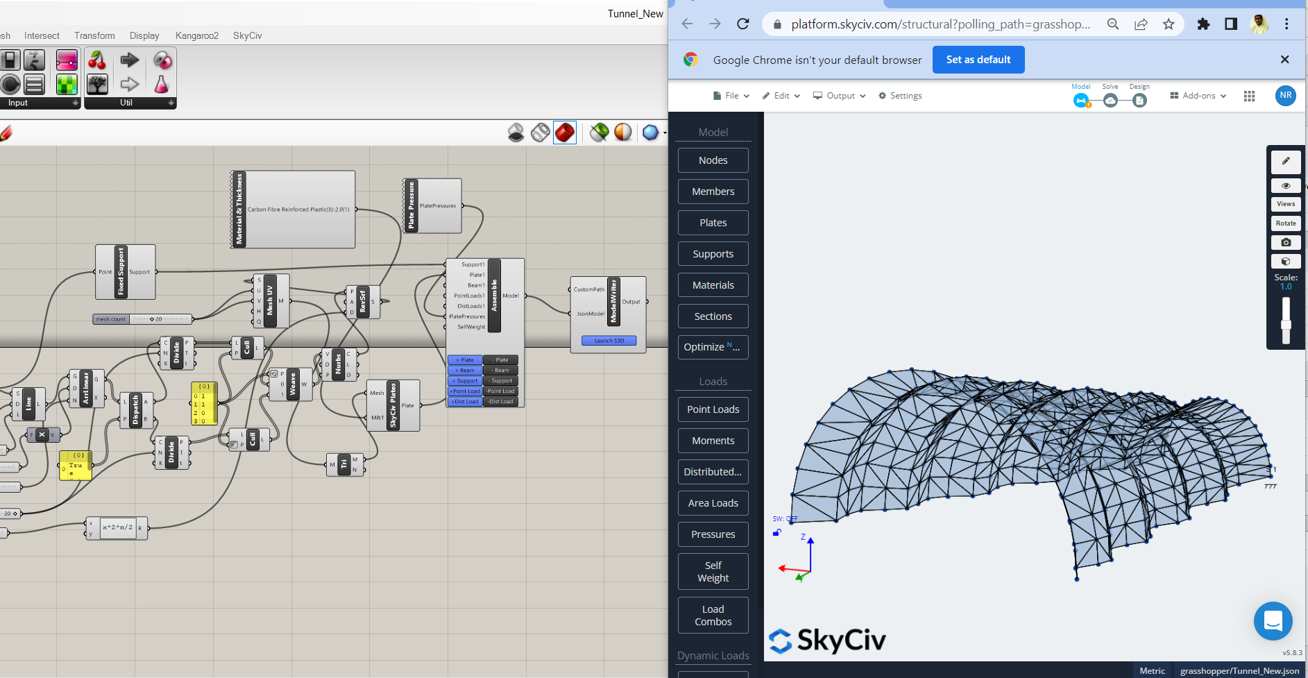
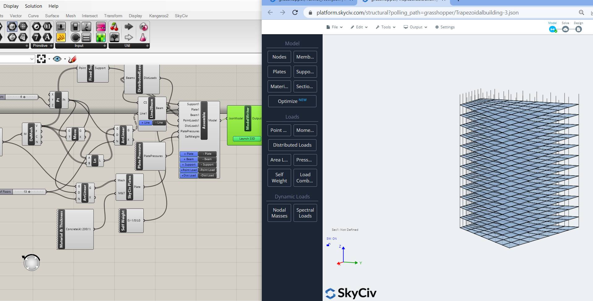
- The model is ready for writing the script in JSON format using the tool called “ModelWriter” which will launch the model in SkyCiv Structural 3D
- The JSON which is formed can be fetched in the SkyCiv’s, S3D platform where the analysis API will be sent to the structural solver. User can see the elements, rendered view, mesh, tag numbers etc etc in S3D for the geometry which was modelled in GH and collaborated using the SkyCiv plugin
Function List
Geometry:
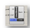
Line2Beam
Converts straight segments into structural beam elements. The input requirement for this components is always all straight lines which has a particular start and end node edges of the meshed geometry. Multiple Beams can be added and connected under this component by using respective ‘+’ button available in input part of component. You can also remove the components by clicking on ‘-’ button available in input part of component.
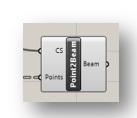
Point2Beam:
Converts two or more points into structural beam elements. Points can be inputted in form of output from arc/circle/curve/radial grid functions.
Plates:
Converts triangular/ rectangular meshed geometry into Structural Plate Elements (either 3 nodes or 4 nodes depending upon the mesh type)
In this version of the plugin, only the coplanar plates are considered. The plate component shall be analysed based on Mindlin’s plate theory. Plates will interpreted in two forms viz plates (parent plate) and meshed plates.
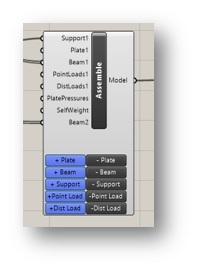
Assemble:
Assembles the entire structural model (Beams &/ Plates) declared in a particular geometry along with supports, loads and section property.
Output of support, loads (depending upon the load type) and cross section shall be connected to the input of this component. Output of self-weight shall also have to be connected under this component. Multiple Beams/Supports/Loads can be connected under Assemble by using respective ‘+’ button available in input part of Assemble component. You can also remove the components by clicking on ‘-’ button available in input part of Assemble component.
Supports:
Fixed support: To define restraint condition as “FFFFFF” for rotation in x, y & z axis respectively & translation in x,y & z axis respectively
3DPin Support: To define restraint condition as “FFFRRR” for rotation in x, y & z axis respectively & translation in x,y & z axis respectively
Pinned XY Support: To define restraint condition as “FFFFRR” for rotation in x, y & z axis respectively & translation in x,y & z axis respectively
Roller Y Support: To define restraint condition as “FRFRRR” for rotation in x, y & z axis respectively & translation in x,y & z axis respectively
Spring Y Support: To define restraint condition as “FSFRRR” for rotation in x, y & z axis respectively & translation in x,y & z axis respectively
Roller X Support: To define restraint condition as “RFFRRR” for rotation in x, y & z axis respectively & translation in x,y & z axis respectively
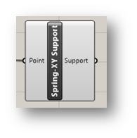
Spring XY Support: To define restraint condition as “FFFFRS” for rotation in x, y & z axis respectively & translation in x,y & z axis respectively
Loads:
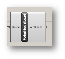
Nodal Load:
Input the Point Load in form of concentrated load which can act at any position on the length of the Beam Elements or at Nodes:
User needs to right click on the component and then fill up the details of the load values and position as per the snapshot below.
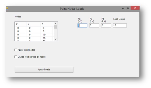
Sign convention of load input is as positive ‘+’ upwards. Load Group can be the name of the desired Load case. Users can also specify whether they want to apply this force to all nodes shown or divided across all the nodes. This will ensure loads are correctly applied, regardless of whether the number of loads changes.
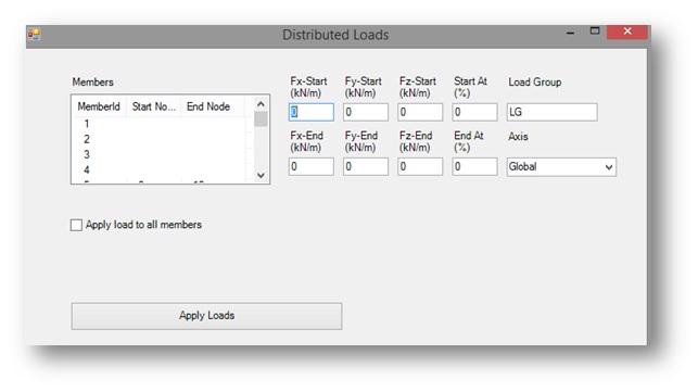
Distributed Load:
Apply distributed loads. Input “Distributed Load” for the Beam Elements
It can be applied as Uniformly Distributed Load or Uniformly varying load.
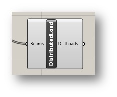
User need to right click on the component and then fill up the details of the load values and position as per the snapshot below.
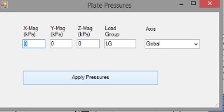
Pressure:
Input the “Uniform Pressure Load” for the plate elements.
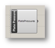
User need to right click on the component and then fill up the details of the load values and position as per the snapshot below.
Sections:
This component is used define the material and section property for “BEAM ELEMENT”
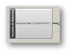
Right click on the Sections & Materials to input the choice of cross section and materials as per the snapshot below.
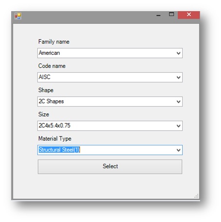
SkyCiv Plugin offers variety of choices as an in-built library to the user for assigning cross section and material.
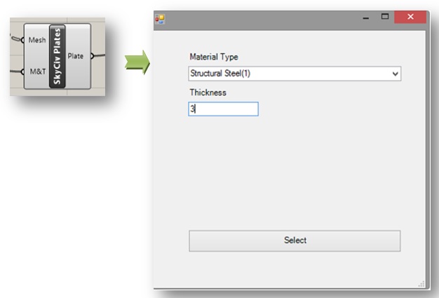
Material & Thickness:
This component can be define the material and Thickness for “PLATE ELEMENT”. Right click on the SkyCiv plate component and then, user can input the plate thickness and select the desired choice of material for the plate.
Output:
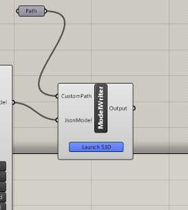
ModelWriter: Representation of structural model in JSON (JavaScript Object Notation) format. The output from the Assemble component needs to be passed to the input of ModelWriter. ModelWriter will allow the user to launch their Grasshopper Model directly in S3D. Any changes to the model in grasshopper will instantly come through in S3D.
ModelWriter also has an option for user to specify the custom path ( the directory) to which the output will be written. This is normally not required and the default settings would be sufficient but in some cases where user doesn’t have control over the default path or in some access issues, this would be beneficial.
For selecting the custom path, we will have to select directory as shown below
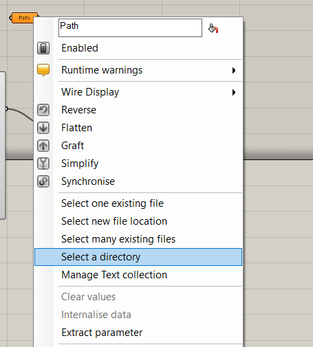
Once the directory is selected , we can give output of Path to the ModelWriter.
Sample Files
Here are some structural Grasshopper Models to help you can download to help you get started:
Tunnel.gh (above)
RectangularBuilding.gh
Flatslabbuilding.gh
Trapezoidalbuilding-3.gh (below)
Troubleshooting
It’s possible you’ll experience the following error when trying to link your Grasshopper model to SkyCiv Structural 3D:
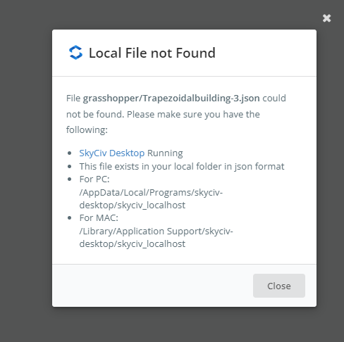
Please try the steps in the error message. If the error continues, please visit our documentation on our Local File Link for more information.