How to model catenary cables in SkyCiv Structural 3D
Creating Cables
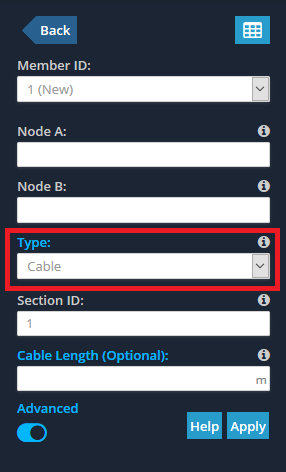
Cables are created in the same way as Members. To start, turn on the ‘Advanced’ button of the Member properties and simply select ‘Cable’ as the Member Type as shown in the image below.
It is important to note that when creating cables, you are effectively drawing the chord of the cable (i.e. a straight line joining Node A and Node B) rather than the catenary cable itself. The software will work out the catenary effects and sagging automatically, so there is NO need to create a series of smaller cable elements to represent the actual cable shape.

Specifying Pre-Tension and Sag
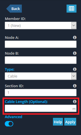
The software allows you to enter a cable length. If you enter a length that is less than the chord length (i.e. the distance between Node A and Node B of the cable member) then you can pre-stress the cable. Likewise if you enter a length that is larger than the chord length, the cable will be un-strained and sagging initially.
NOTE: Entering this field is OPTIONAL. If you do not specify a cable length then the initial chord length will be taken as the cable length (i.e. it is not pre-stressed and not sagging).

Pretension Force
It is possible to enter a cable length that approximates a pretension force. We can do this using the formula for axial displacement:
 After the cable analysis runs the final axial force in the cable may be different to the force yielded by the formula above. This is because the force above is the “initial” force in the cable before the analysis takes place (i.e. the pretension). If you want to aim for a specific force in the cable at the end of the analysis then you may need to perform a series of iterations to get the intial pre-tension force correct.
Cable Loading
Cables are special types of members that must be loaded according to the rules below:
- Any point loads must be applied to the end nodes of a cable (i.e. they cannot be member loads along the cable). If you wish to apply a point load along the cable, split the cable into two cables and then apply the load at the junction of the two cables.
- Distributed Loads applied to a cable MUST be uniform (i.e. the start and ending magnitudes of the DL must be equal).
- All cables must be loaded with at least one uniform distributed load (UDL) or self-weight. If neither of these are found, the solver will apply a small “Artificial UDL”.
- Cables can only take Distributed Loads in the global Y-axis. This means that if Self-Weight is applied to the structure, it must be in the Y-axis. If you would like to see DLs in any direction please let support@skyciv.com know
Additional Notes
- Cables must be solved by Non-Linear Analysis. If any other method is used, the solver will automatically be switched to Non-Linear.
- Cables are purely axial (in tension). All cables are assumed to be pinned, so entering end-fixities (Node A and Node B Fixity) is not required.
- Convergence of your structure when cables are used can be difficult due to the non-linear behavior.
- Cables cannot be accurately modelled with tension-only truss members. Catenary cable elements like those used in accordance with this page are the most accurate way to model cables.
- SkyCiv has a free tension cable calculator, which is also available as a paid version under your Professional Subscription
Having issues solving?
Cables can be tricky to solve, so SkyCiv created a guide on some easy tips to solve a cable which features 5 things you can try to get your model to solve. In short, these include:
- Check diameter size
- Check Cables are Not Over/Under Loaded
- Reduce your Convergence Accuracy
- Add Extra Supports
- Check Your Other Members
Otherwise, if you have a Professional Account our engineers can help via live support, where we can see your model in real-time.


