Lateral Pile Stability
The SkyCiv Lateral Pile Stability tool is designed to aid engineers in the design of poles and piles subject to lateral loading.
The tool supports common methods for lateral pile stability calculations:
- Broms
- Brinch Hansen
The calculator provides useful shear force and bending moment diagrams for the pile and can be used to calculate the minimum embedment length required for a pile subject to lateral loading and moments. The tool can also be used to calculate a utilisation or a maximum horizontal force for a particular arrangement.
The Brinch Hansen method allows for multiple soil layers to be provided and assumes a rigid and infinitely strong pile. Broms method allows for a single granular or cohesive material and can take into consideration plastic hinge formation in the pile.
This tool was built with reference to the following two textbooks:
- Reese, L.C. Single Piles and Pile Groups Under Lateral Loading, 2011.
- Brinch Hansen, J. The Ultimate Resistance of Rigid Piles Against Transversal Forces. Bulletin No. 12, Geoteknisk Institut (The Danish Geotechnical Institute), Copenhagen, 1961.
About the Pile Stability Calculator
What is a Pile Stability Check ?
 In foundation engineering it is a common requirement to calculate the minimum embedment length required for a pole or pile in order to resist lateral loading. For instance consider a light pole that may have minimal vertical actions since it only supports its self weight but significant lateral actions due to wind and a large cantilever. Even if our light pole is infinitely strong there is a risk that lateral loading could cause failure in the supporting soil resulting in our light pole toppling over. As a result we should check that our pole is embedded sufficiently deep for the forces and geology in our problem.
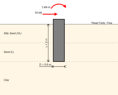
The lateral pile stability is mainly dependent on the following factors:
- Length of pile (L)
- Diameter of pile (D)
- Soil cohesion (c’)
- Soil internal friction angle (φ)
- Soil unit weight (γ)
- Horizontal Load at top of pile (H)
- Moment at top of pile (M)
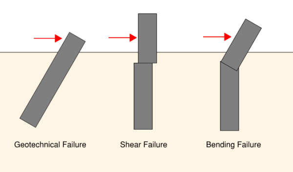
Pile Stability Failure Modes
The pile can fail due to lateral loading in three different ways. The modes of failure are:
- geotechnical failure (occurs for a strong pile without sufficient embedment)
- structural shear failure (unlikely but a pile could fail in shear, a shear force diagram is provided so that shear forces can be reviewed)
- structural bending failure (more likely, but if a plastic hinge is taken into consideration using Broms method this might be okay)
For the remainder of this blog we will primarily be concerned with geotechnical failure for a pile. We will also determine the maximum shear force and bending moment on the pile so that we can then check the structural capacity is sufficient.
How to calculate lateral pile passive earth resistance?
As a lateral force begins to act on a pile the passive resistance of a soil will begin to develop at the base of the pile. The way that the passive soil resistance is calculated is one of the main differences between Broms and the Brinch Hansen method.
As an upper bound we can assume that the entire passive resistance acts on a single side. If our pile cannot resolve these forces then it is not stable and no further checks are required. A diagram for the different pile stability methods assuming the passive resistance is all on one side of the pile is shown below.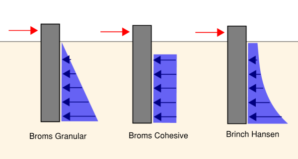
For brinch hansen the calculations are a bit complicated to do by hand but for broms solving the equations by hand is more possible with the passive earth pressure calculated from the following formulae.
For Broms Granular:
- Pz = 3 * D * γ * z * Kp
- Kp = tan2(45 + φ/2)
For Broms cohesive:
- Pz = 9 * cu * D (where the top 1.5 * D depth of the pile has Pz = 0)
How to calculate lateral pile stability?
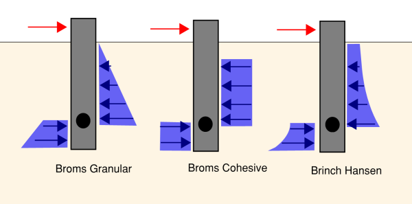
After we have calculated the earth pressures along the pile we now need to consider how the pile might rotate. At a certain depth there will be a point that the pile rotates about. Below the rotation point passive pressures would act on the left of the pile in the same direction as the applied force and above the rotation point passive pressures would act on the left of the pile in the opposite direction to the applied force. This rotation point is an unknown that we will need to solve for.
We can solve for the rotation point using our boundary conditions for the problem. We expect that for the pile to be stable the sum of all our horizontal forces should be 0. We also expect that the sum of our moments is also 0, in the case of our pile we would anticipate 0 moments at the bottom of the pile and a moment of M at the top of the pile.
The Brinch Hansen method involves summing the horizontal forces to 0 such that the shear force diagram starts at the horizontal load and ends at a 0 at the bottom of the pile. Once we have found the rotation point through this method we can interpret the bending moment diagram to see what the maximum moment the pile could sustain for this shear force.
Broms method is slightly different in that the sum of the bending moments is considered in order to determine the rotation point. The shear force diagram is then reviewed to see what the maximum lateral load is that pile can sustain.
How to apply reduction factors for lateral pile stability?
Reduction factors such as a factor of safety can be used to reduce the passive earth pressures that are considered to act on the pile. Once the passive pressures have been reduced to an allowable amount then calculations can proceed as normal.
Which Pile Stability Method to Use ?
Brinch Hansen method is good when the pile can be assumed to be infinitely rigid. If plastic hinges need to be considered or calculations wish to be compared to hand calculations the Broms calculation method is more suitable.
How to Increase the Piles Lateral Capacity
Depending on the failure mode of the pile different approach's might be suitable in order to increase a piles capacity.
One approach might be to increase the diameter of the pile. For example for a circular hollow steel fence post it is common practice to embed it in a concrete foundation with a larger diameter than the pole. This helps the fence to be stable against lateral loading.
Another approach is to increase the embedment length of the pile. Where the pile is not failing structurally this will increase the amount of passive earth pressure acting on the pile and will help to increase the piles resistance.
A more difficult method is to increase the geotechnical material strength which often is not practical. This could mean using controlled fill around a post or even cement stabilised fill if required.
Skyciv Lateral Pile Capacity Calculator Features
The SkyCiv lateral pile capacity calculator has many features and capabilities:
- Lateral Loads and Moments: The calculator accounts for the impact of lateral loads and moments, providing an accurate assessment of the foundation's stability under such conditions.
- Inbuilt optimizer: Automatically optimize for the minimum length of a pile or maximum horizontal load
- Methods: Use either Broms or Brinch Hansen method and compare results between both calculations
- Multiple Soil Layers: For the Brinch Hansen calculation use multiple soil layers
- Plastic hinges: For Broms method show the effect of plastic hinges on the load distribution in the pile
Related Tools
Related Pages
About SkyCiv
SkyCiv offers a wide range of Cloud Structural Analysis and Design Software for engineers. As a constantly evolving tech company, we're committed to innovating and challenging existing workflows to save engineers time in their work processes and designs.
