Reinforced Concrete Beam Calculator
The SkyCiv Reinforced Concrete Beam Calculator allows engineers to design reinforced concrete beams to the ACI 318-19. Reinforced concrete beams are a composite section that combine the benefits of concrete and steel in an economic way. The composite nature of a reinforced concrete beam makes design calculations more rigorous than other sections and the Quick Design Concrete Beam Calculator provides an easy tool for engineers to assess capacities of rectangular beams and T-beams.
About Concrete Beam Design
What Are Beams?
Beams are horizontal structural members in a building that play a crucial role in transferring loads to vertical supports like columns and walls. In reinforced concrete structures, beams primarily resist bending moments and shear forces caused by gravity loads from floors and roofs. They may also experience torsion and lateral forces depending on the building’s design and external conditions. Unlike girders, which typically support other beams, concrete beams directly support floor slabs and distribute loads efficiently. Common cross-sections for concrete beams include rectangular, T-shaped, and L-shaped profiles, often reinforced with steel to enhance strength and ductility. Proper reinforcement detailing is essential to prevent cracking and ensure durability, making beams a key component in concrete construction.
Why Use Reinforced Concrete Beams?
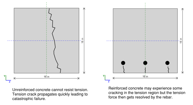
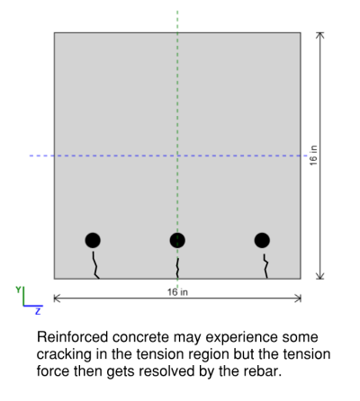
Beams are exposed to large bending forces, which (generally) induce compression at the top of the beam and tension at the bottom of the beam. An economic solution to deal with this would be to use a material that is good in compression at the top of the beam (i.e. concrete) and a material that is good in tension at the bottom of the beam (i.e. steel). Reinforced concrete columns utilise the compression strength of concrete and tension strength of rebar for an economic beam design. They are widely used in construction due to their durability, fire resistance, and ability to support heavy loads.
How To Design For Reinforced Concrete Beams
The composite nature of a reinforced concrete beam makes it more complex to analyze from first principles. In steel design, we can simply determine the section modulus and multiply it by the yield strength to find the bending capacity. However, in reinforced concrete, the section is not homogeneous, and the presence of two different materials requires a deeper understanding of the stress-strain relationship. To accurately assess how the beam behaves and determine its failure mode, we need to look into the stress-strain graph to analyze the interaction between concrete and steel reinforcement.
If we consider combined bending and compression forces acting simultaneously we would also need to draw an interaction diagram to interpret the strength of the member. Luckily most beams are not required to resist large axial forces and the ACI 318-19 lets us ignore the effects of axial load on our stress-strain diagram if the axial force is less than a certain limit (Pu < 0.10 * f'c * Ag , see clause 9.5.2). For more information about interaction diagrams you can read here.
Reduction Factors For Reinforced Concrete Beam Design According to ACI 318-19
The ACI 318-19 requires that non-prestressed concrete beams are tension controlled. This requirement means that if a reinforced concrete beam does fail in bending it will fail in a ductile manner giving warning to those around the structure before it completely fails.
The section is classified in relation to the net tensile strain (εt) which is the strain in the reinforcement closest to the tension face:
- Tension Controlled : εt ≥ εty + 0.003
- Transition : εty < εt < εty + 0.003
- Compression Controlled εt <= εty
The strength reduction factor (φ) used for the moment, axial force or combined moment and axial force is dependent on how the section is classified and for a tension controlled beam the reduction factor is always 0.9.
How To Calculate The Axial Capacity of a Concrete Beam
The pure axial capacity of a concrete beam can be calculated the same as it is for a concrete column. However if we are dealing with combined bending and compression we will need to make sure that the axial forces is less than 0.10 * f'c * Ag for a concrete beam otherwise we will need to use an interaction diagram. To learn about this see this page on concrete columns for more.
How To Calculate The Bending Capacity of a Reinforced Concrete Beam
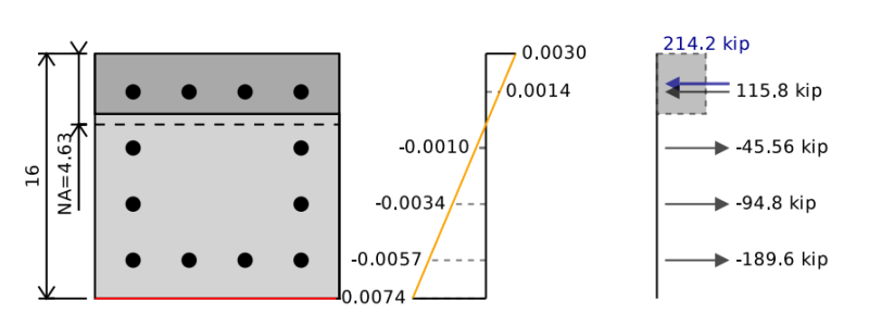
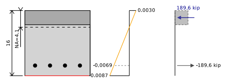
The bending capacity of our reinforced concrete beam is equivalent to the point of pure bending on an interaction diagram. To determine the bending capacity we need to balance the compression and tension forces in our section to be equal to 0 (i.e. no axial load acting on the beam). We can then take moments about the neutral axis of the section in order to find the bending capacity of the reinforced concrete beam.
To do this we can assume a neutral axis position and keep iterating and shifting it until we find the stress-strain diagram that corresponds with pure bending. In the example below we can see that if we add up the forces in the concrete and the steel we get a total net force of 0 kip, but a net moment of 255 kip-ft which represents our concrete beams ultimate bending capacity. When we reduce this by our 0.9 safety factor we get a design bending capacity of 229 kip-ft.
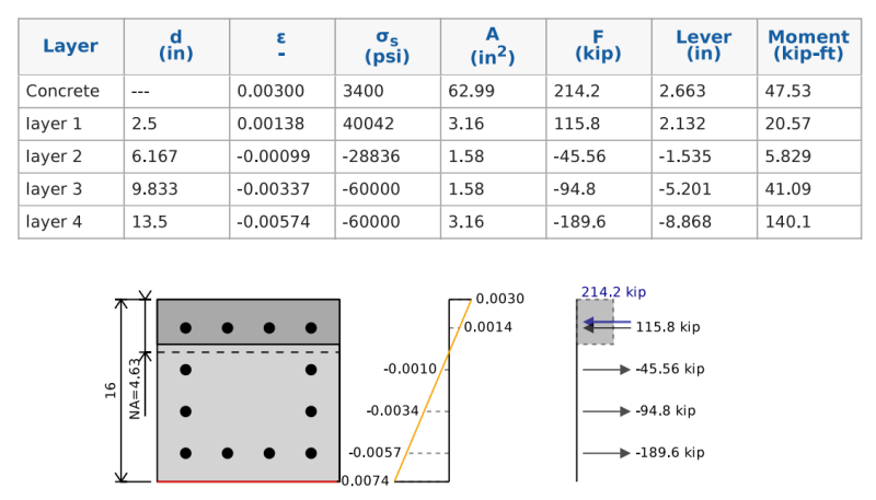
How To Calculate The Force On Reinforcement
Calculating the stress and force in the reinforcement is similar to how we calculated the pure tension strength. Our stress is equal to our strain times our Young's Modulus but is limited by our yield stress.
σ = min( εt * E , εty * E )
We can then determine the force on our bars by multiplying the stress by the area of the bars in this row. To simplify calculations where we have multiple bars with the same strain we can group these all together.
Ft = σ * A
We need a way to distinguish between our force being in compression or tension. We could use Ft and Fc to denote the different forces but for this example and in the SkyCiv Calculator we will use a sign notation of negative representing tension and positive representing compression.
How To Calculate The Force On A Concrete Stress Block
Calculating the stress in the concrete portion of a reinforced concrete beam is more complex than the reinforcement due to its nonlinear stress distribution. However, an empirical simplification known as the Whitney Stress Block method allows for easier calculations. This method approximates the nonlinear stress distribution with an equivalent rectangular stress block, making it more practical for structural analysis and design.

The ACI describes this method in section 22.2.2.4.1. We calculate a as:
a = β1 * c
where β1 ranges from 0.65 to 0.85 depending on the compression strength (f'c) of concrete (see Table 22.2.2.4.3).
when we calculate the force on the stress block we always use an effective stress of 0.85 * f'c.
So we can calculate the compression force as:
Fc = 0.85 * f'c * β1 * c
and the force acts at a position a/2 from the extreme compression edge.
How To Calculate Biaxial Bending Capacity for a Rectangular Beam
It is rarer to deal with biaxial loads in a beam compared to a column since a beam is primarily resisting gravity loads and it is expected that a concrete slab on top of it might be designed to resist lateral loads as a diaphragm.
The interaction diagram we have previously looked at was for uniaxial bending of a rectangular reinforced concrete section. We have only considered the bending to be happening about one axis but we could also have minor axis bending. For minor axis bending we would do everything the same except we would rotate the section 90 degrees so instead we would have something like this. Note the red line represents the bottom of the beam.
For biaxial bending we need to rotate our section so that is bending about the plane of its resultant moment. The interaction diagram we would get for this biaxial diagram is only relevant for this particular direction of resultant moment.
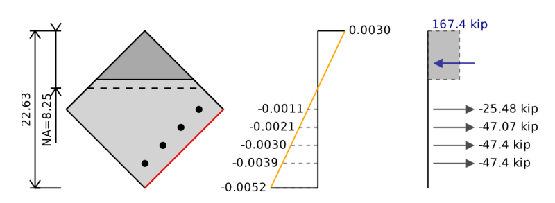
We can follow the same steps as we did for the interaction diagram previously except now we will have different positions for our reinforcement and in the case of a rectangular section in biaxial bending we have a triangular area that is in compression.
Instead of calculating the concrete compression force as:
Fc = 0.85 * f'c * β1 * c
We can instead calculate the concrete compression force as:
Fc = 0.85 * f'c * A
where A is the area in compression above the position a = β1 * c
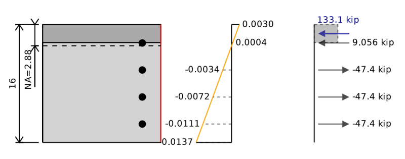
How To Calculate Bending Capacity of a T-Beam
The bending capacity calculations for a T-beam are the same as for a rectangular beam except that we have a larger compression area at the top of the section. This is largely beneficial at providing extra bending capacity since it effectively shifts the centroid of the compression force further from the tension force and results in an increased lever arm for our bending calculations. If however, we have negative bending with tension at the bottom of the beam assessing the structure as a T-beam is unlikely to provide any benefits. It is therefore important that we consider the direction of our bending moment when designing for our reinforced concrete beam and do not simply take the absolute maximum force for our design.
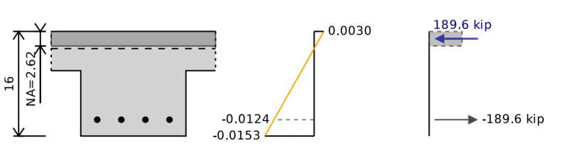
In the image above we see the neutral axis at a position of 2.62' form the compression side of the section however if we remove the benefit of the T-beam the neutral axis shifts and the bending moment capacity is reduced by around 5%.
How To Calculate Shear Capacity of a Reinforced Concrete Beam
In short our concrete shear strength is the combination of our shear strength due to compression and our shear strength due to steel (assuming shear reinforcement is provided). This is expressed as:
Vn = Vc + Vs
where:
- Vc is the shear strength contribution of concrete
- Vs is the shear contribution of steel
- Vn is the total shear strength of the section
For shear strength a reduction factor of φ = 0.75 is always used.
To calculate the contribution of the shear strength we consider an effective width bw and an effective depth d for the cross-sectional area resisting shear failure. The reason we do not use the full section area is that the section may have already partially cracked due to bending in the tension zone which would reduce the area of our section available to resist shear failure.
Concrete Contribution to Shear Strength in a Reinforced Concrete Beam
The actual calculation we use for Vc depends on if our minimum steel criteria has been met or not, so our concrete strength contribution is not entirely dependent from our steel calculations.
The calculation for the concrete shear strength contribution when the area of shear reinforcement is less than the minimum reinforcement of shear area is given by the following equation in table 22.5.5.1:
Vc = 8 λs λ (ρw)^(1/3) * (f'c)^(1/2) + Nu / 6 Ag ) bw d
where:
- λ is the modification factor for lightweight concrete (1 if normal weight concrete is used)
- λs is the size effect modification factor (dependent on d)
- ρw = ratio of tension steel divided by bw d
- Nu is axial load
- Ag is gross cross sectional area
Although it sounds funny, the reason we might have less steel than the minimum shear reinforcement (Av,min) is that the minimum required steel is not always enforced. For example if the shear force Vu < φ * λ * (f'c)^(1/2) * bw * d in a non-prestressed beam then the minimum shear reinforcement is not required to be provided. The full details regarding the minimum shear reinforcement for a concrete beam is provided in section 9.6.3 of ACI 318-19.
If we have more reinforcement than the minimum shear reinforcement then there are two equations provided for calculating the shear strength of concrete which can be found in table 22.5.5.1 of the ACI 318-19.
Steel Contribution to Shear Strength in a Reinforced Concrete Beam
For shear reinforcement we are concerned with the spacing of our shear reinforcement along the length of the beam. This is important to know how many bars of steel a shear plane would intersect.
We can calculate the shear strength due to steel reinforcement as:
Vs = Av * fyt * d / s
where:
- Av = the area of steel intersecting the shear plane
- fyt = the yield strength of shear reinforcement (typically 60000 psi)
- d = the depth to tensile bar centroid
- s = spacing of shear ligatures
If we consider the physical meaning of this calculation is quite easy to follow along. We have the concrete beam already cracked to position d. At position d our shear failure starts at a 45 degree angle running to the top of the beam. The height and width of this shear failure is also of dimension d. Over this dimension d we cross (d/s) bars of steel. We then multiply the area of the bars when they intersect the shear plane and there yield strength to get the overall shear capacity of the reinforcement in the concrete beam.
Related Tools
About SkyCiv
SkyCiv offers a wide range of Cloud Structural Analysis and Design Software for engineers. As a constantly evolving tech company, we're committed to innovating and challenging existing workflows to save engineers time in their work processes and designs.
